En
En
 De
De Fr
Fr Ru
Ru Es
Es Pt
Pt It
It Ar
Ar Se
Se Nl
Nl Jp
Jp Tw
Tw Gr
Gr Th
Th Fi
Fi Ko
Ko Pl
Pl Cn
Cn Tr
Tr No
No Dk
Dk Il
Il My
My Hu
Hu Hi
Hi
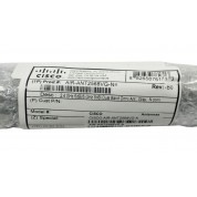
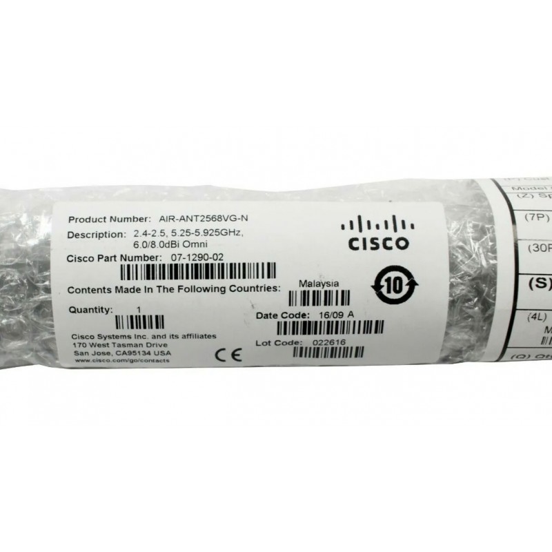
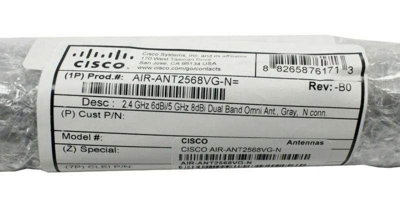
Cisco AIR-ANT2568VG-N Aironet Dual-Band Omni-directional Antenna 07-1290-02
- Brand: Cisco
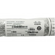
- Part Number: AIR-ANT2568VG-N
- Condition: Factory New Sealed
-
Availability: In Stock
- Ships: Typically within 2 Business Days
- Warranty: 3 Years
Cisco AIR-ANT2568VG-N Aironet Dual-Band Omni-directional Antenna 07-1290-02
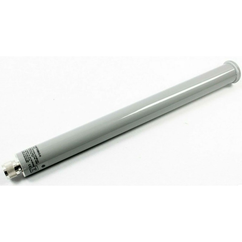
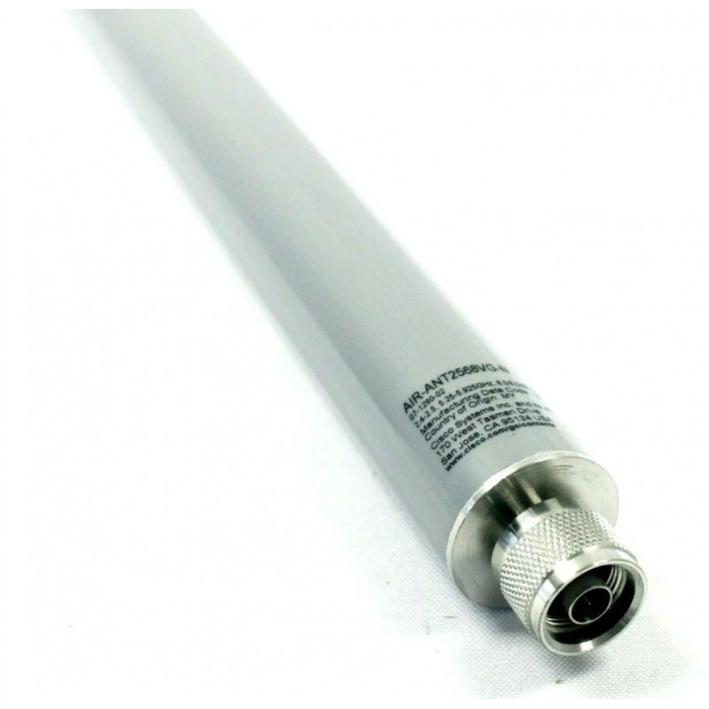
This document describes the Cisco Aironet AIR-ANT2568VG-N and the Cisco Aironet AIR-ANT2568VG-NS dual-band omni-directional antennas and provides specifications and mounting instructions. The antennas are designed for outdoor use with Cisco Outdoor Access Points with radios operating in the 2.4–GHz and 5–GHz frequency bands.
The Cisco AIR-ANT2568VG-NS is a self-identifying antenna having circuitry that enables Cisco access points (APs) to self-identify the antenna. This antenna has an in-built EEPROM that the APs read and automatically configure the antenna type and the gain in the wireless controller.
Technical Specifications
- Antenna Type: Omni-directional
- Operating Frequency Range: 2400–2483 MHz; 5150–5925 MHz
- VSWR
- 1.5:1 (2400–2483 MHz)
- 2:1 (5150–5925 MHz)
- Nominal Input Impedance: 50 Ohms
- Gain
- 6 dBi (2400–2483 MHz)
- 8 dBi (5150–5925 MHz)
- Polarization: Vertical
- Azimuth Plane Ripple: 2 dB (Max)
- Elevation Plane 3 dB Beamwidth
- 24° (2400–2483 MHz)
- 11° (5150–5925 MHz)
- Azimuth Plane 3 dB Beamwidth: Omni-directional
- Length: 14.8 in (377 mm)
- Diameter: 1.25 in (31.75 mm)
- Weight: 7.2 oz. (204.1 g)
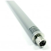
- Connector: N-Male
- Operational Temperature: -22–158°F (-30–70°C)
- Storage Temperature: -40–185°F (-40–85°C)
- Water/Foreign Body Ingress: IP67
- Wind Rating (Operational): 100 mph (161 kph)
- Wind Rating (Survival): 136 mph (218 kph)
System Requirements
This antenna is designed for use with the Cisco Aironet Outdoor Access Points.
Safety Precautions
Warning: Do not locate the antenna near overhead power lines or other electric light or power circuits, or where it can come into contact with such circuits. When installing the antenna, take extreme care not to come into contact with such circuits, as they may cause serious injury or death. For proper installation and grounding of the antenna, please refer to national and local codes (e.g. U.S.: NFPA 70, National Electrical Code, Article 810, Canada: Canadian Electrical Code, Section 54). Statement 280
For your safety, read and follow these safety precautions.
- Before you install an antenna, contact your Cisco account representative to explain which mounting method to use for the size and type of antenna that you are about to install.
- Find someone to help you—installing an antenna is often a two-person job.
- Select your installation site with safety, as well as performance, in mind. Remember that electric power lines and phone lines look alike. For your safety, assume that any overhead line can kill you.
- Contact your electric power company. Tell them your plans and ask them to come look at your proposed installation.
- Plan your installation carefully and completely before you begin. Each person involved in an installation should be assigned to a specific task and should know what to do and when to do it. One person should be in charge of the operation to issue instructions and watch for signs of trouble.
- When installing your antenna, follow these guidelines:
- Do not use a metal ladder.
- Do not work on a wet or windy day.
- Dress properly: wear shoes with rubber soles and heels, rubber gloves, and a long-sleeved shirt or jacket.
- If the assembly starts to drop, move away from it and let it fall. Because the antenna, mast, cable, and metal guy wires are all excellent conductors of electrical current, even the slightest touch of any of these parts to a power line completes an electrical path through the antenna and the installer.
- If any part of the antenna system should come in contact with a power line, do not touch it or try to remove it yourself. Call your local power company to have it removed safely.
- If an accident should occur with the power lines, call for qualified emergency help immediately.
Installation Notes
The antenna is designed to connect to a dedicated antenna port on the access point. No special tools are required to install the antenna.
The antenna is resistant to the full range of outdoor environments. After the antenna is attached to the access point, seal the connections to prevent moisture and other weathering elements from affecting performance. Cisco recommends using a coax seal (such as CoaxSeal) for outdoor connections. Silicone sealant or electrical tape are not recommended for sealing outdoor connections.
Choosing a Mounting Location
The antenna is designed to create an omni-directional broadcast pattern. To achieve this pattern, the access point should be mounted clear of any obstructions to the sides of the radiating element. If the mounting location is on the side of a building or tower, the antenna pattern is degraded on the building or tower side.
Generally, the higher an antenna is above the ground, the better it performs. A practice is to install your antenna about 5 to 10 ft (1.5 to 3 m) above the roof line and away from all power lines and obstructions.
Tools and Equipment Required
No tools are required to mount the antenna to the access point. However, you may need a ¾ in. (19 mm) open end or combination wrench (or adjustable wrench) to remove the antenna port covers.
For information about tools required to mount the access point, see the appropriate access point documentation.
Mounting the Antenna
To connect the antenna to the access point:
- If necessary, remove the antenna port cover.
- Align the antenna N-type connector with the appropriate antenna port.
- Gently push the antenna into the port.
- Hand tighten the antenna to the port using the metal knurled ring only.
Warning: Do not use the plastic body to tighten. This may damage the antenna.
For more information of this AIR-ANT2568VG-N, please visit Cisco website:
https://www.cisco.com/c/en/us/td/docs/wireless/antenna/installation/guide/ant2568vgn.html
| This AIR-ANT2568VG-N is 100% genuine Cisco product. It won't have any compatibility problem with your Cisco devices. And the Cisco AIR-ANT2568VG-N Aironet Dual-Band Omni-directional Antenna 07-1290-02 is factory new with original packaging. Buy it now and enjoy risk free purchase with fast worldwide delivery from GenuineModules.com |