 En
En
 De
De Fr
Fr Ru
Ru Es
Es Pt
Pt It
It Ar
Ar Se
Se Nl
Nl Jp
Jp Tw
Tw Gr
Gr Th
Th Fi
Fi Ko
Ko Pl
Pl Cn
Cn Tr
Tr No
No Dk
Dk Il
Il My
My Hu
Hu Hi
Hi
How to make a patch cable?
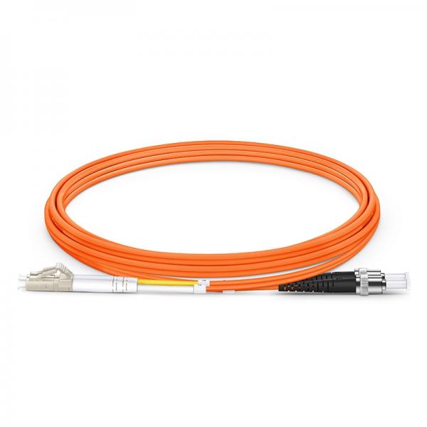
Selecting the right cable and connectors for patch cables
To make a patch cable, you will need to follow a few steps. However, before diving into the process, it is crucial to understand the importance of selecting the right cable and connectors for patch cables.
When it comes to choosing the cable, it is recommended to opt for Category 5e or Category 6 cables. These cables are designed to handle high-speed data transmission and provide better performance compared to older versions. Additionally, they are more resistant to crosstalk and interference.
Next, you need to select the appropriate connectors for your patch cable. The most common type of connector used for patch cables is the RJ-45 connector. These connectors have eight pins and are compatible with Ethernet connections. It is essential to ensure that the connectors are of good quality to maintain a reliable connection.
Now, let's move on to making the patch cable. Start by stripping the outer jacket of the cable to expose the individual twisted pairs. Carefully untwist and straighten the wires, making sure they are in the correct order according to the wiring standard you are using (T568A or T568B).
Once the wires are in order, trim them to the appropriate length, leaving enough room to insert them into the RJ-45 connector. Insert the wires into the connector, ensuring that each wire goes into the correct slot. Use a crimping tool to secure the wires in place.
Finally, test the patch cable using a cable tester to ensure that all the connections are working correctly.
In conclusion, making a patch cable involves selecting the right cable and connectors, preparing the wires, and crimping them into the connector. By following these steps, you can create reliable patch cables for your networking needs.
Measuring and cutting the cable to the desired length
To make a patch cable, the first step is to measure and cut the cable to the desired length. This is crucial in ensuring that the cable fits perfectly and eliminates any excess or loose ends.
To measure the cable, start by determining the length needed for your specific setup. Consider the distance between the devices you're connecting and any other factors that may affect the cable length. It's always a good idea to add a few extra inches to the measurement to allow for any adjustments or future changes.
Once you have the measurement, use a sharp cable cutter or wire stripper to cut the cable to the desired length. Make sure to cut the cable straight and avoid any fraying or damage to the inner wires.
After cutting the cable, you will need to strip the insulation from both ends. Use a wire stripper to carefully remove the outer insulation, exposing the inner wires. Be cautious not to cut into the wires themselves.
Next, untwist the pairs of wires and arrange them according to the wiring scheme you're using. This could be either T568A or T568B, depending on your preference or the standard being followed in your network.
Finally, insert the wires into the appropriate connectors, ensuring that each wire is fully seated and making proper contact. Use a crimping tool to secure the connectors onto the cable, providing a strong and reliable connection.
By following these steps, you can easily make a patch cable that is customized to your desired length and specifications. It's important to double-check your work and test the cable before deploying it to ensure optimal performance and connectivity.
Stripping the outer insulation and shielding from the cable
To make a patch cable, the first step is to strip the outer insulation and shielding from the cable. This is done to expose the inner wires and prepare them for termination. The process involves carefully removing the outer layer of insulation without damaging the inner wires.
Start by measuring the desired length of the patch cable and cut the cable accordingly. Then, use a wire stripper tool to remove the outer insulation. Place the cable into the appropriate notch on the stripper tool and squeeze the handles to score the outer layer. Rotate the tool around the cable to create a clean cut, and then gently pull the insulation away from the cable.
Once the outer insulation is removed, you will see the shielding. This shielding is often made of foil or braided wire and is used to protect the inner wires from interference. Use a utility knife or a pair of scissors to carefully cut and remove the shielding, being cautious not to damage the inner wires.
After the shielding is removed, you will be left with the inner wires. These wires are typically color-coded, with each color representing a specific signal or function. Use a wire stripper tool to remove a small portion of the insulation from each wire, exposing the bare copper.
At this point, the cable is ready to be terminated with connectors, such as RJ45 plugs for Ethernet cables. Follow the appropriate termination instructions for the connectors you are using, ensuring that each wire is correctly aligned and crimped into place.
It is important to note that the process of making a patch cable may vary slightly depending on the specific type of cable being used, such as Cat5e or Cat6. Additionally, advancements in cable technology may introduce new techniques or tools to simplify the process. Therefore, it is always recommended to refer to the manufacturer's instructions or seek the latest information to ensure proper cable construction.
Testing the patch cable for proper continuity and functionality
To make a patch cable, you will need the following materials: Ethernet cable, RJ45 connectors, a wire stripper, a crimping tool, and a cable tester. Follow these steps to create your patch cable:
1. Start by cutting the Ethernet cable to the desired length. Ensure that the cable is long enough to reach from one device to another without any tension or strain.
2. Use the wire stripper to remove about an inch of the outer insulation from both ends of the cable. Be careful not to damage the inner wires while stripping the outer sheath.
3. Untwist the individual wire pairs and arrange them according to the T568A or T568B wiring standard. This standard ensures proper connectivity and compatibility between devices.
4. Trim the wires to an even length and insert them into the RJ45 connector in the correct order. Make sure each wire goes into the appropriate slot, and that the wires are fully inserted and reach the end of the connector.
5. Use a crimping tool to firmly press the RJ45 connector onto the cable, securing the wires in place. Apply enough pressure to ensure a solid connection but avoid over-crimping, which may damage the connector.
6. Repeat the process on the other end of the cable, ensuring consistency in wiring and crimping.
7. Once both ends are completed, use a cable tester to check for proper continuity and functionality. The tester will indicate if there are any wiring errors or connectivity issues.
Testing the patch cable for proper continuity and functionality is crucial to ensure it will work effectively. The cable tester will help identify any miswiring or faulty connections that could hinder data transmission. It is recommended to use a tester that can check for both wire continuity and signal integrity.
In the latest point of view, advancements in cable testing technology have made it easier to detect and diagnose issues with patch cables. Some cable testers now offer more comprehensive testing capabilities, such as identifying the specific wiring standard used and detecting crosstalk or interference. Additionally, there are cable testers available that can provide detailed reports and documentation of the test results, making troubleshooting and maintenance more efficient.
Overall, making a patch cable involves careful attention to detail and proper wiring techniques. Testing the cable is an essential step to ensure its reliability and functionality in transmitting data between devices.

 Cat7 Flat SSTP Shielded 10Gbps Ethernet Network Patch Cable")
 Cat7 Flat SSTP Shielded 10Gbps Ethernet Network Patch Cable")
 Cat7 Flat SSTP Shielded 10Gbps Ethernet Network Patch Cable")


