 En
En
 De
De Fr
Fr Ru
Ru Es
Es Pt
Pt It
It Ar
Ar Se
Se Nl
Nl Jp
Jp Tw
Tw Gr
Gr Th
Th Fi
Fi Ko
Ko Pl
Pl Cn
Cn Tr
Tr No
No Dk
Dk Il
Il My
My Hu
Hu Hi
Hi
Optical Fibers and Optical Connectors
15.12.21
0 Comments
Optical Fibers
Optical fibers are classified into single-mode fibers and multimode fibers.
Single-mode fibers have a diameter of 5-10 μm and transmit laser in one mode under a specified wavelength. These fibers support a wide frequency band and a large transmission capacity, so they are used for long-distance transmission. Most single-mode fibers are yellow, as shown in Figure 6-23.
Multimode fibers have a diameter of 50 μm or 62.5 μm and transmit laser in multiple modes with a specified wavelength. They have a small capacity and their performance is inferior to that of single-mode fibers, making them suitable to short-distance transmission.
In the latest cabling infrastructure of ISO/IEC 11801, multimode fibers are classified into four categories: OM1, OM2, OM3, and OM4.
OM1: traditional 62.5/125 μm multimode fibers. OM1 fibers have a large core diameter and numerical aperture, and provide high light gathering ability and bending resistance.
OM2: traditional 50/125 μm multimode fibers. OM2 fibers have a small core diameter and numerical aperture. Compared with OM1 fibers, OM2 fibers provide higher bandwidth because they significantly reduce the modal dispersion. When transmitting data at 1 Gbit/s with 850 nm wavelength, OM1 and OM2 fibers support maximum link lengths of 220 m and 550 m, respectively. OM1 and OM2 fibers can provide sufficient bandwidth within a distance of 300 m. Generally, OM1 and OM2 fibers are orange, as shown in Figure 6-24.
OM3: new-generation multimode fibers, with longer transmission distances than OM1 and OM2 fibers.
OM4: laser optimized multimode fibers with 50 μm core diameter. OM4 is an improvement to OM3 and only increases the modal bandwidth. OM4 fibers provide 4700 MHz*km of modal bandwidth, whereas OM3 fibers provide only 2000 MHz*km of modal bandwidth. Generally, OM3 and OM4 fibers are light green, as shown in Figure 6-25. You can identify OM3 and OM4 fibers by their labels or printed marks.
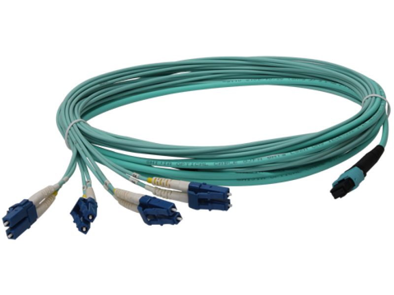
MPO fibers are used for 40G and 100G optical modules. An MPO fiber consists of multiple multi-mode fiber strands, and each multi-mode fiber strand provides one laser transmission channel. Some fiber suppliers produce 8-strand MPO optical fibers, while some suppliers produce 12-strand or 24-strand MPO fibers.
A 40G optical module uses four channels to transmit laser and four channels to receive laser. That is, a total of eight channels are required for a 40G optical module. 8-core and 12-core MPO fibers use the same definition of fiber channels. Therefore, they are equivalent in functionality when connecting to 40G optical modules.
When 100G optical modules are used, choose MPO fibers according to the following principles:
For CFP optical modules, choose 24-strand fibers for the CFP-100G-SR10 module and 8-strand or 12-strand fibers for other modules.
Choose 8-strand or 12-strand fibers for QSFP28 modules.
Optical Connector
Optical connectors are used to connect optical fibers of the same type. Table below lists common optical connectors.
| Connector Type | Picture |
| LC/PC |
|
| SC/PC |
|
| FC/PC |
|
| ST/PC |
|
| MTRJ/PC |
|
| MPO |
|


Ceramic Ferrule End Face
Based on the return loss, the end faces of the fiber's ceramic ferrule are classified into three types: PC, UPC, and APC, as shown in below picture.

Polishing types of the fiber's ceramic ferrule end face
| Polishing Type | Return Loss | Characteristics |
| PC | -35 dB | Polished with a slight curvature |
| UPC | -50 dB | Dome-shaped |
| APC | -60 dB | Polished with an 8-degree angle |
In principle, optical fibers with different ceramic ferrule end faces cannot be directly connected through optical connectors. Interconnection between PC and UPC connectors does not cause permanent physical damage to them. The structure of APC end faces is totally different from that of PC end faces. Therefore, if fibers with APC end faces and fibers with PC end faces are connected through optical connectors, their ceramic ferrule end faces will be damaged. To connect them together, use a fiber jumper. This, however, adversely affects the transmission performance.
Comments
Note: HTML is not translated!
Submit comment


")
")


